
Remember me


The project was divided into three main stages: first, the design and characterization of the metamaterial; second, simplified simulations using single elements with different magnitudes of shield impedances in a rectangular phantom; and third, the simulation of four-element antennas in a more realistic simulation including the complete scanner and the realistic body model DUKE [17]. All simulations were performed with CST Studio Suite 2021.
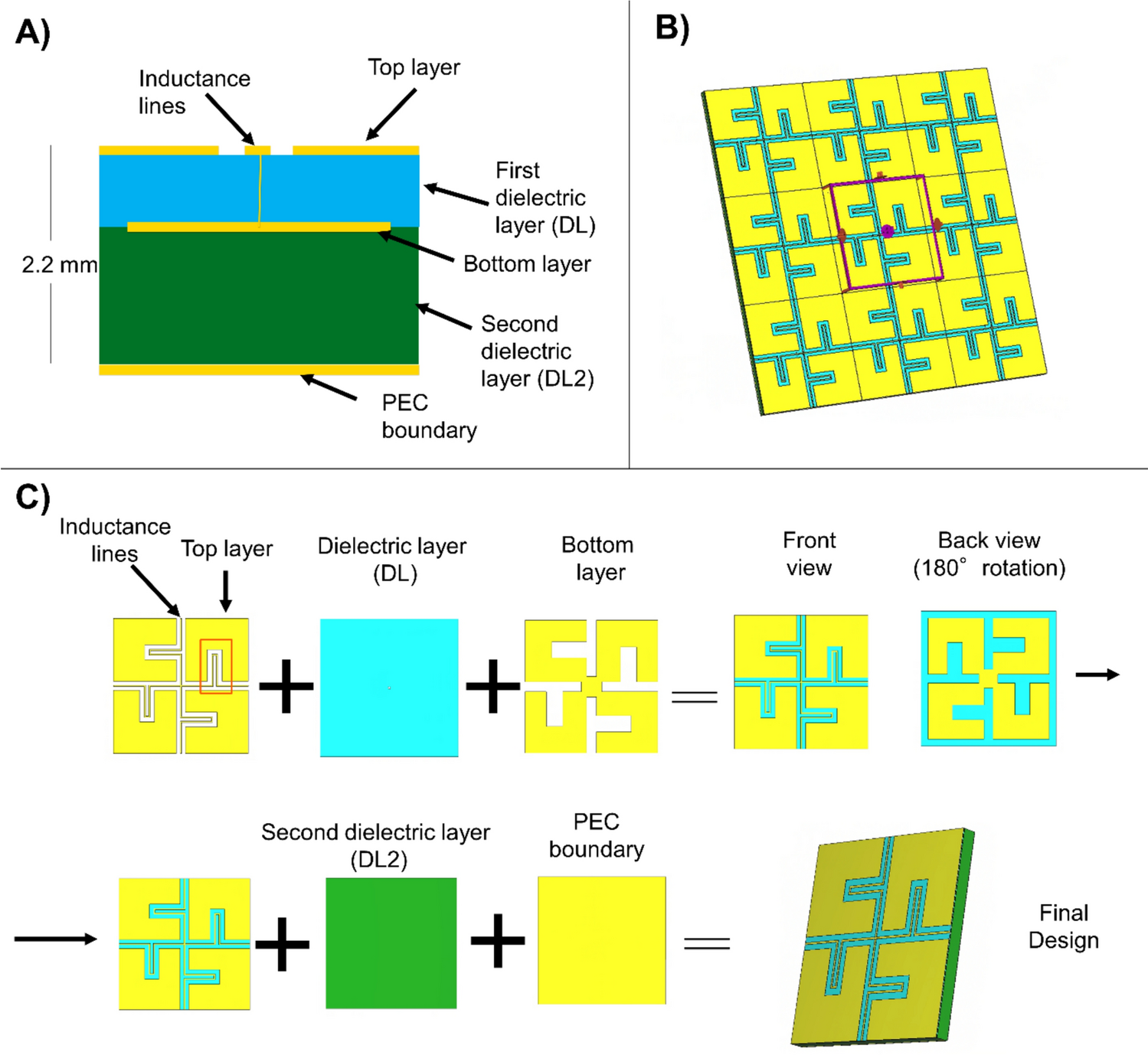
Design of the metamaterialThe metamaterial design was based on the cross-shaped structure from Chen et al. [16]. It was restructured to minimize its thickness due to space constraints, as the gap between the gradient coil and patient bore liner of our 7 T system is 34 mm. Thus, leaving some distance between the elements, the configuration allows less than 10 mm for the metamaterial and the cables (5.4 mm). To achieve this, the dielectric layers of the metamaterial were moved closer together and the conductor wires were extended by adding meanders, while part of the copper of the top layer reduced. This ensured that the LC ratio of Eq. 2 remained constant at the working frequency of 297.2 MHz while reducing the overall thickness of the metamaterial. The total thickness of the metamaterial was set to 2.2 mm, consisting of 3 copper layers with intervening dielectric material. The top floating layer facilitates easy connection to nearby PCBs, simplifying the manufacturing process. The full structure can be seen in Fig. 1.
Fig. 1
A Schematic view of the metamaterial layers in a side view of the structure. B Metamaterial structure in a frontal view for a 3 × 3 array of the unit cells. C Layer by layer decomposition of the metamaterial, the red rectangle in the first subfigure highlights the meander elements in the inductance lines
Floquet port excitations, which model wave propagation at various incidence angles by introducing phase shifts across the boundaries of a periodic unit cell, were used to represent an infinite array using a single unit cell, significantly reducing simulation complexity. This allows us to tune the structure to the desired resonance frequency (297.2 MHz) by adjusting parameters such as the unit cell size, layer thickness, or other design values listed in Table 1, to achieve high impedance. The influence of material choice on the resulting impedance is discussed in Section. "Discussion and outlook". A co-planar array of these unit cells was used to study current mitigation within the material, a key property of PMC boundary. Additionally, a dispersion diagram was generated using the eigenmode solver in CST to examine how transverse electric (TE) and transverse magnetic (TM) modes propagate. This analysis was restricted to the irreducible Brillouin zone, the smallest segment of the reciprocal space that fully captures all unique wave behavior due to the symmetry of the periodic structure.
Table 1. Parameters and values for the metamaterial tuned to working frequency of 297.2 MHzSingle-element simulationsSimplified electromagnetic simulations (Fig. 2) in a rectangular phantom (500 mm × 500 mm × 230 mm, \(\sigma\)=0.57 \(\frac}}}}\), \(\epsilon_\)=44, \(_\)=1, \(\rho\)= 1000 \(\frac}}^}\)) using different magnitudes of shield impedance (from \(^\) to \(^\)) were performed for a half-wave dipole with length of 466 mm and a short dipole with a length of 50 mm. The antennas were normalized to 1W accepted power. Additionally, the simulations were used to study the loading effect of the bore liner on the antennas, and the SAR efficiency and SARmax were obtained.
Fig. 2
Diagram of single element simulation for remote antenna. The simulations were performed both with and without the bore liner
Four-element simulationsMore realistic simulations with a four-channel array were performed, including the body model Duke [17] and the entire scanner structure. The scanner design was based on the Siemens Magnetom 7 T with passively shielded magnet and AS095 gradient coils. The bore liner has an inner radius of 59.5 cm, and the total length of the scanner is 3 m. The patient table was also included, as shown in Fig. 3. The metamaterial was added as a cylindrical shield between the bore liner and the gradient coils (simplified as PEC) and simulated as a material with the corresponding impedance.
Fig. 3
Transversal view of the simulation setup. From the exterior to the interior layer: magnet, gradient coils (Siemens AS095), HIS/PEC shield, antennas (red dots), bore liner, and patient table with patient
AntennasFour antenna types were tested for the array, positioned as shown in Fig. 3.
Each antenna was tuned with an LC circuit to minimize input reflection. The tuning ensured that the S-parameters (\(_}\)…\(_}\)) were at least -15 dB when the elements were placed within either a PEC or HIS shield and normalized to 1W stimulated power.
Dipoles are well known for their uniform RF distribution [18], ease of integration into multichannel arrays [19], and enhanced deep tissue penetration [18], making them a good standard. A 466 mm dipole antenna with a central excitation gap of 20 mm was used. The length was chosen so that the antenna’s maximum field was centered within the geometry when tuned without metamaterial.
A smaller version of the half-wave dipole was used to study whether the metamaterial could increase the field of view and the possibility of using smaller antennas. The total length was reduced by one-third to 310.6 mm. Smaller versions, like the one used in Section. "Single-element simulations", were found to be heavily loaded by the bore liner and were therefore unsuitable for the study (see "Results").
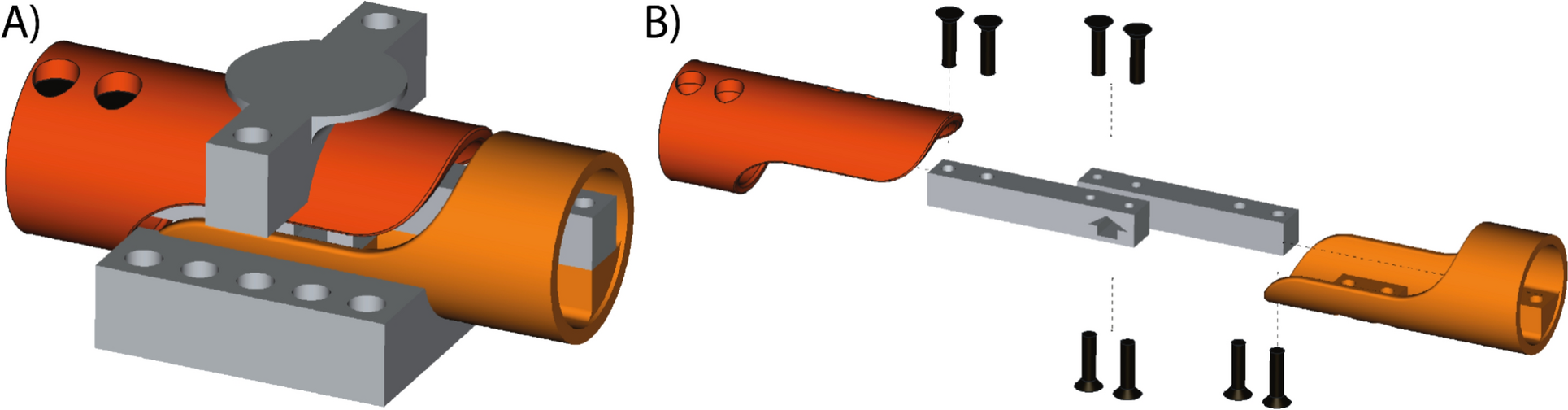
Raaijamakers et al. [20] showed that using a fractionated dipole with four lumped elements and central feeding (Fig. 4, left) could improve SAR efficiency compared to plain dipoles. To investigate this, two cases proposed in their paper were studies: an array with lumped elements of 5 pF and another with lumped elements of 75 nH.
Fig. 4
Left: Fractionated Dipole. Red ports indicate feeding points and blue points lumped elements. Right: Meander stripline backed with the metamaterial shield. Central feeding was achieved by two central vias (circles in the center of the antenna)
Adding capacitors to the antenna is similar to decreasing the effective length of the antenna, therefore, leading to a more localized current distribution in the center of the antenna as it is expected from a short dipole. However, \(_^\) at depth remains unchanged in comparison to a plain dipole of the same size making it a better alternative than a short dipole [20]. In contrast, inductors increase the effective length and can make the antenna support up to two wavelengths.
Both cases (5 pF and 75 nH) were studied by Raaijamakers et al. [20]. 5 pF was chosen because their simulated results indicated an increase in \(_\)+ without a large compromise in SAR efficiency, while 75 nH was selected because it was the inductance that they empirically tested.
Modern whole-body imaging techniques such as RF shimming, SENSE [21, 22], and TIAMO [23] require multiple RF coils. As a result, coupling between the elements becomes an important parameter. Therefore, elements like the microstrip line with meander elements investigated by Rietsch et al. [24] are an interesting approach to reduce coupling due to the extended electrical length of the microstrip line thanks to the meander elements at the end of the structure (Fig. 4, right). This type of element is centrally fed with two ports and contains lumped elements at the two ends connected to the PEC backplane behind the metamaterial.
In contrast to the other elements, the metamaterial was not added as a cylindrical shield around the meanders due to space constraints caused by the dielectric layers of the antenna, where the curvature of the cylinder would interfere with the antenna structure, but instead a smaller plate was used to fit in the geometry of the scanner as well as minimizing the necessary space as shown in Fig. 4.
Comments (0)