
Remember me
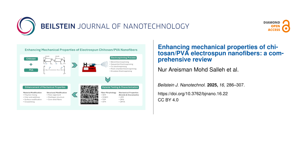
In recent years, electrospinning has attracted significant attention from scientists because of its easy process . Electrospinning can fabricate polymeric fibers ranging from the micro- to the nanoscale . It is an easy, simple, and low-cost technique that does not require heat, an important factor for sensitive compounds . Electrospun nanofibers exhibit a large surface area, high porosity, and small pore size, making them useful for a wide range of applications, as shown in Figure 1. Chitosan/polyvinyl alcohol (PVA) electrospun nanofibers have many applications, including water treatment, biomedical uses, and wound healing . However, a drawback of electrospun nanofibers is their mechanical properties . Electrospun nanofibers typically exhibit poor mechanical properties due to their high porosity, random fiber arrangement, and weak interactions at the cross-points of the nanofibers . In this review, we focus on the background of the electrospinning process, the properties of chitosan/PVA electrospun nanofibers, and fabrication techniques, including the effects of various parameters and post-treatment methods. We also review the characterization of chitosan/PVA electrospun nanofibrous membranes and the methods to improve their mechanical properties, applications, and future perspectives.
![[2190-4286-16-22-1]](https://www.beilstein-journals.org/bjnano/content/figures/2190-4286-16-22-1.png?scale=2.0&max-width=1024&background=FFFFFF)
Figure 1: Applications of electrospun nanofibers .
Review BackgroundElectrospinning is an advancement of electrospraying, where electric forces are used to disperse fine aerosols from a polymer solution, a technique invented in 1747 by Abbé Nollet . During electrospinning, fluid is drawn through an electrically charged spinneret with a conical shape at the tip from which a jet emerges . Based on Zeleny’s research, Geoffrey Taylor described in 1964 that the meniscus’ critical half-angle approaches 49.3° immediately before collapse. Thus, in a strong electric field, the tip of a polymer solution or melt extruded from a capillary changes from a spherical to a conical shape, the so-called Taylor cone .
The parameters involved in the electrospinning process can be divided into three categories, namely, electrospinning, solution, and environment. For electrospinning, factors such as applied electric field, distance between the needle and collector, flow rate, and needle diameter affect the fabrication of the nanofibrous sample. Solution parameters include the types of solvent, polymer concentration, viscosity, and solution conductivity. Finally, environmental parameters include relative humidity and temperature .
Chitosan, a widely utilized material in electrospun nanofiber membranes, is derived from the crystalline microfibrils of crustaceans, including crabs and prawns. It is biodegradable and exhibits a high capacity for adsorbing heavy metals and radionuclides . However, chitosan exhibits limited mechanical stability, is sensitive to pH variations, and tends to swell . To improve the spinnability of chitosan during the electrospinning process, it is commonly blended with other polymers, such as PVA . Additionally, PVA contributes to reducing the crystallinity of the chitosan structure .
Because of their unique and exceptional properties, nanofibrous membranes have become prominent materials for a wide range of applications . Throughout their time of use, electrospun fibers are exposed to environmental stresses in each of these applications. These forces could cause the nanofibers to fail or become permanently deformed, potentially rendering the entire device inoperative. Thus, before using these materials in particular fields, it is essential to take their mechanical properties into consideration .
Electrospun nanofibrous membranes typically have poor mechanical characteristics. The materials used, the non-Newtonian fluids in the electrospinning solutions, and the nanofibers’ random orientation are the three primary factors of the poor mechanical performance of electrospun nanofibers. For example, collagen is one substance used in electrospinning that has low strength . Its loose structure and weak composition are the reasons behind its inherent poor mechanical performance. Electrospinning solutions with non-Newtonian fluids come next. They exhibit unstable properties, including irregular fluid jet movement, variations in surface tension, and sensitivity to external parameters such as temperature, humidity, and airflow. These factors can disrupt the uniformity of the fiber formation. When the fiber jets are drawn in the direction of the electric field force, the polymer chains in the fibers are not properly aligned, resulting in non-uniform mechanical and structural properties . The incomplete crystallization of the fibers caused by the short and weak stretch process gives the fibers poor mechanical properties . Last, there is the fibers’ random orientation. When an external force is applied to electrospun nanofibers, the load is distributed across a network of thousands of fibers. However, because of their random orientation, the force is not evenly distributed. In some cases, the load is concentrated on a single fiber, which can result in significant stress on that fiber and weaken the overall structure .
With advancements in technology for producing nanofibers through electrospinning, various methods and techniques have been developed to enhance the mechanical properties of electrospun nanofibers. The objective of this review is to explore current techniques and methods for improving the mechanical properties of electrospun nanofibers, thereby enhancing their application in various fields.
Materials compositionChitosan is an intriguing material derived from chitin. Because of its promising properties, it has attracted significant attention from researchers . It is abundantly found in the shells of crustaceans and is the most abundant biopolymer after cellulose . Figure 2 shows the chemical structure of chitosan.
![[2190-4286-16-22-2]](https://www.beilstein-journals.org/bjnano/content/figures/2190-4286-16-22-2.svg?scale=2.0&max-width=1024&background=FFFFFF)
Figure 2: Chemical structure of chitosan.
Chitosan has been studied extensively and is recognized as a prominent material in the fields of medicine, food, and water treatment. Table 1 shows the properties applications of chitosan that have been studied.
Table 1: Properties of chitosan studied in various applications.
Industry Property/application References medical health care wound healing anti-oxidant antimicrobial antifungal water treatment nanofiltration chelating heavy metal ion removal toxic chemical food membrane as food packagingAmong the crucial factors in the electrospinning process is the solubility of the polymer . Chitosan is soluble in organic acids such as diluted aqueous acetic, formic, and lactic acids, but it is insoluble in water, alkali, and most mineral acid systems. Additionally, chitosan is soluble in mixtures of water, methanol, ethanol, and acetone , making it feasible for the electrospinning process. Unbound amino groups make chitosan a positively charged polyelectrolyte in acidic media, resulting in high solubility . This phenomenon makes it difficult to electrospin chitosan because of its high viscosity . Moreover, the formation of strong hydrogen bonds in a 3D network contributes to difficulties in the mobility of polymeric chains when an electric field is applied . Because of these factors, chitosan can only be electrospun in the presence of a spinnable polymer such as PVA . A previous study has demonstrated the viability of adding PVA as an additional component to chitosan . This addition reduces the repulsive interactions between polycations, thereby decreasing chain entanglement and promoting fiber formation . A summary of the applications of chitosan/PVA nanofibers is provided in Table 2.
Table 2: Applications of chitosan/PVA electrospun nanofibers.
Sample Applications References nanoclay-reinforced electrospun chitosan/PVA nanocomposite nanofibers biomedical chitosan/polyvinylpyrrolidone/PVA electrospun nanofiber removal of heavy metal ions and organic pollutants electrospun nanofibers of chitosan/polyvinyl alcohol/UiO-66/ nanodiamond adsorbents for wastewater remediation and organic dye removal electrospun chitosan/poly(vinyl alcohol)/glycerol nanofibers skin care biaxial electrospun nanofibers based on chitosan-poly (vinyl alcohol) and poly (ε-caprolactone) modified with CeAlO3 nanoparticles wound dressing materials electrospun chitosan-polyvinyl alcohol nanofiber dressings loaded with bioactive ursolic acid diabetic wound healing antioxidant peptide-loaded electrospun chitosan/poly(vinyl alcohol) nanofibrous mat food packagingPVA is a synthetic polymer widely utilized in various industries because of its versatile properties. Its water solubility allows for a wide range of applications, while its carbon atom backbone ensures chemical stability and compatibility with diverse environments. Figure 3 shows the chemical structure of PVA. PVA is known for its biodegradability, allowing it to disintegrate in both aerobic and anaerobic environments. This feature is crucial for industries concerned about the environment because it mitigates the long-term effects of PVA waste on ecosystems. Research on PVA biodegradation further supports its status as an environmentally friendly polymer .
![[2190-4286-16-22-3]](https://www.beilstein-journals.org/bjnano/content/figures/2190-4286-16-22-3.svg?scale=2.0&max-width=1024&background=FFFFFF)
Figure 3: Chemical structure of PVA.
The mechanical properties of PVA depend on several factors, such as molecular weight and retained moisture . Dry, fully hydrolyzed PVA exhibits ductile properties with an elongation at break of 25% . However, PVA has low mechanical strength under wet conditions. Because of its solubility in water, its applications are limited, and it can only be used as an internal layer in multilayer structures. A convenient strategy to overcome these limitations, without losing the advantages of PVA such as biodegradability, is to blend PVA with stiff and water-insoluble biodegradable polymers such as chitosan .
Fabrication techniquesNanofibers can be fabricated using different methods such as direct drawing, template synthesis, phase separation, self-assembly, and electrospinning. Electrospinning is considered the most versatile and widely used technique for nanofiber fabrication, offering greater control over fiber structures, higher productivity, simplicity, lower cost, and potential for industrial use . Electrospinning involves applying a high voltage to a polymer solution delivered through a nozzle or capillary . The electrostatic charge builds up at the tip of the droplet, and when the repulsive force of the charges overcomes the droplet’s surface tension, a cone-like jet, known as the Taylor cone, forms, and the resultant solidified fibers are collected on a grounded (or oppositely charged) collector. The collector used can be stationary or moving, with different configurations affecting the alignment of the deposited fibers. A typical electrospinning setup configuration is shown in Figure 4.
![[2190-4286-16-22-4]](https://www.beilstein-journals.org/bjnano/content/figures/2190-4286-16-22-4.png?scale=2.0&max-width=1024&background=FFFFFF)
Figure 4: Schematic diagram of the electrospinning process for the fabrication of nanofibers.
Electrospinning is a versatile technique for producing microfibers and nanofibers, but the process, especially with the conventional single-nozzle electrospinning, has several limitations. Some of the challenges include low throughput, which hinders industrial-scale production, poor fiber uniformity, and limited control over fiber alignment and orientation . Random fiber alignment and orientation, in addition to low crystallinity of electrospun structures, tend to result in poor mechanical strength . To address the challenges of conventional electrospinning, researchers have explored alternative approaches with distinct fiber-producing capabilities such as centrifugal electrospinning, alternating current electrospinning, near-field electrospinning, multinozzle electrospinning, and needleless electrospinning. Other improvement efforts include modifications on the solution or melts used for electrospinning, innovative designs of the electrospinning setup and components, and various post-treatment methods. These advancements aim to improve productivity, safety, and control over fiber properties, potentially enabling broader industrial applications of nanofibers .
The use of a single polymer material as the electrospinning solution produces fibers with limited functional properties . This limits the practical use of the fibers, especially to solve advanced issues that arise in line with the rapid growth in research and advanced technologies. Multicomponent fibers, composed of two or more materials, are designed to enhance the functionality and properties of the fibers, thereby broadening their applications in areas such as antibacterial treatments, water purification, and biomedical engineering . Fabrication of multicomponent polymer nanofibers like chitosan/PVA can be carried out through methods such as blend electrospinning, sequential electrospinning, co-electrospinning, and emulsion electrospinning.
Blend electrospinningBlend electrospinning refers to the electrospinning of a single solution or mixture containing more than one material or polymer, which makes up one single-phase homogeneous liquid. Polymer blending allows for the creation of novel materials through the incorporation of the unique properties of the component polymers . In blend electrospinning, the preparation of a homogenous solution is crucial in ensuring the formation of uniform fibers during electrospinning, and some of the important parameters to take into consideration are the molecular weight of each component, solubility of the solvents, temperature, and the polymer blend ratio . The straightforward approach in preparing the solution is by directly mixing both polymers in the solvent system, which can be either a single solvent or a mixture of solvents (Figure 5a). The polymers can also be prepared separately in separate solvent systems , and the solutions are subsequently mixed to form the final solution before electrospinning (Figure 5b). The latter involves more steps but minimizes the risk of incomplete dissolution or phase separation due to different solubility requirements of each polymer . Nevertheless, the instabilities can still occur when blending the two solutions if the solvents are incompatible.
![[2190-4286-16-22-5]](https://www.beilstein-journals.org/bjnano/content/figures/2190-4286-16-22-5.png?scale=2.0&max-width=1024&background=FFFFFF)
Figure 5: Electrospinning polymer blend solutions by (a) mixing two polymer materials in a single solvent system and (b) mixing two solutions prepared from separate solvent systems.
Sequential electrospinningSequential electrospinning is a method where two or more polymer solutions are electrospun consecutively to form a hierarchically ordered structure consisting of meshes of different materials . Also called layer-by-layer electrospinning, the general steps of preparing multilayered composites using this method involve layering fibers upon fibers through multiple steps, as shown in Figure 6. The functionality of the overall structure depends on the different properties exhibited by each layer. In bioactive encapsulation and controlled release applications, for example, multilayered membranes can be used to regulate the release time of substances by exploiting the surface properties and interactions between hydrophobic and hydrophilic layers . This sequential method of producing composite fibers is generally easier than the other methods as the different materials are electrospun separately, eliminating concerns related to compatibility of the materials and solvents during preparation as well as the interaction between the fiber jets during the electrospinning process. However, the entire procedure can become more time- and labor-consuming as more steps are required.
![[2190-4286-16-22-6]](https://www.beilstein-journals.org/bjnano/content/figures/2190-4286-16-22-6.png?scale=2.0&max-width=1024&background=FFFFFF)
Figure 6: Two-step sequential electrospinning for the fabrication of multilayered nanofibers.
Co-electrospinningCo-electrospinning refers to the electrospinning of multiple solutions from multiple nozzles simultaneously (also known as multinozzle or simultaneous electrospinning). Like sequential electrospinning, multiple polymer solutions are prepared separately, but instead of layering one after another, the different materials are electrospun simultaneously, as shown in Figure 7. This method of electrospinning is usually preceded by single-nozzle electrospinning of each component separately to find the optimum parameters before running them concurrently . Besides combining different fibrous materials, this multinozzle method can also be used to incorporate nanoparticles into the nanofiber structures through simultaneous electrospinning and electrospraying . In co-electrospinning, the interaction between charged jets for nozzles that are positioned close to one another may cause jet repulsion for nozzles of the same polarity, which can cause difficulties in collecting the fibers. Nozzles that are placed on opposite sides as shown in Figure 6a can overcome this problem, but it requires a larger working area, and the use of rotating collectors is usually necessary. Other approaches include using oppositely charged nozzles so that the fibers attract instead of repelling each other, or using auxiliary electrodes to control the electric field and concentrate the flow of fiber jets into a smaller deposition area .
![[2190-4286-16-22-7]](https://www.beilstein-journals.org/bjnano/content/figures/2190-4286-16-22-7.png?scale=2.0&max-width=1024&background=FFFFFF)
Figure 7: Co-electrospinning with two nozzles (a) facing each other on the opposite sides and (b) next to each other on the same side of the collector.
Multichamber electrospinningMultichamber electrospinning incorporates special nozzle designs to fabricate multicomponent fibers, where a single nozzle is partitioned into separate chambers, with the most popular technique being the coaxial electrospinning. Coaxial electrospinning involves the use of a compound coannular nozzle to fabricate core–shell fibers . For a two-solution system, the solution from the inner tube forms the core and the annular solution from the outer tube forms the shell of the resultant fibers. Although it appears as if only a single nozzle is used, the method essentially involves simultaneous electrospinning from multiple coaxial nozzles of different diameters; hence, it is sometimes considered a subcategory of co-electrospinning. The special design of the coaxial electrospinning spinneret enables fiber formation from polymer solutions that are considered almost impossible to electrospin on their own . In this case, the shell fluid, which is usually the solution with better electrospinning capability, will assist in the entrainment of the core fluid to form core–shell fiber jets. Three-material core–sheath fibers are reported to have been successfully electrospun using triaxial nozzles . Other design variants include having multiple nozzles enclosed within one outer nozzle, producing fibers with multiple cores encapsulated by a sheath material .
Another type of electrospinning based on a specialized spinneret is split-nozzle electrospinning, also referred to as side-by-side electrospinning, where the nozzle contains a wall or partition along the central axis, which separates two different solutions into two separate chambers within the nozzle . The two different solutions should possess similar electrical conductivity for the materials to eject as a single jet without any phase separation. This technique can be regarded as a variant of coaxial electrospinning in which spinneret is conceptualized as two half-cylindrical nozzles joined together. The fibers formed from the process are attached side-by-side instead of a core–shell structure. Figure 8 illustrates the different types of fibers formed using multichamber nozzles.
![[2190-4286-16-22-8]](https://www.beilstein-journals.org/bjnano/content/figures/2190-4286-16-22-8.png?scale=2.0&max-width=1024&background=FFFFFF)
Figure 8: Multichamber nozzles used to prepare multicomponent electrospun fibers.
Emulsion electrospinningEmulsion electrospinning is similar to blend electrospinning in principle, but instead of a single homogenous mixture, the emulsion is based on multiple phases that are not mixed during the process . To prepare an emulsion, two immiscible fluids, for example, oil and water are mixed with the use of stabilizers . Emulsion electrospinning is a potentially sustainable method of electrospinning as it limits the use of organic solvents. This method also allows for the fabrication of core–shell fibers from a standard nozzle, without the need of coaxial nozzles. Emulsion electrospinning is a promising method for fabricating nanofibers with advantages such as protection, controlled release, and high loading efficiency for food, pharmaceutical, and biomedical applications .
Table 3 summarizes some of the main advantages and disadvantages of the different electrospinning methods employed to fabricate multicomponent nanofibers. The choice of method to use depends on the specific application and requirements of the fiber structure, considering the trade-offs between different techniques.
Table 3: Advantages and disadvantages of different electrospinning methods for multicomponent fiber fabrication.
Fabrication technique Advantages Disadvantages blend electrospinning simple setup and process as only a single nozzle is required; allows for mixing of multiple polymers in each fiber strand difficulty in preparing stable homogeneous solution; limited control over individual polymer distribution within fibers sequential electrospinning ease of electrospinning without considering the interaction with the other material/solution; ability to form multilayer fibrous structure possibility of weak layer adhesion; may be time-consuming because of discontinuity of the process simultaneous multinozzle electrospinning potentially time-saving because of simultaneous fiber production, ability to produce hybrid fiber mats and yarns; good fiber adhesion due to interwoven fibers complex setup requiring multiple nozzles; possibility of processing issues and non-uniform fiber distribution due to electric field and jet interaction multichamber electrospinning ability to create distinct fiber morphologies such as side-by-side, core–shell, and encapsulated structures; saves space as the nozzles are partitioned internally requires specially designed nozzles; difficulty to control the cross-sectional distribution of the multicomponent fibers; possibility of forming only a single-material fiber because of suppressed core fluid entrainment;Chitosan nanofibers offer numerous advantages, including biocompatibility, biodegradability, and similarity to the extracellular matrix (ECM) . Electrospinning pure chitosan without any other precursor material, however, presents significant challenges due to its inherent properties. Chitosan has high viscosity and low solubility in most solvents, and it tends to form gels, which complicates the electrospinning process. Repulsive forces between ionic groups due to high electric fields during electrospinning also tend to form discontinuous chitosan fibers . Solvents used in the electrospinning of pure chitosan include hydrochloric acid, acetic acid, formic acid, hexafluoro isopropanol (HFIP), trifluoroacetic acid (TFA), and dichloromethane (DCM). TFA is a good solvent to produce homogenous fibers, but it is a highly toxic organic substance . Because of the difficulties regarding the processing of chitosan, it is almost always mixed with another material prior to electrospinning, with polyethylene oxide (PEO) and PVA as popular precursor material candidates. Other disadvantages of chitosan nanofibers include low mechanical strength and poor solubility in water .
PVA is a good precursor material in electrospinning as it helps in improving the spinnability of fibers by reducing repulsive forces within charged polymer solutions . While PVA nanofibers offer advantages such as ease of fabrication and biocompatibility, applications of single-material PVA nanofibers are usually limited by their poor mechanical properties, high water solubility and hydrophilicity, and low thermal stability . The disadvantages often necessitate the combination of PVA with other materials or the application of post-processing techniques such as cross-linking or coating for performance improvement . As a countermeasure, Rafieian et al. proposed electrospinning only PVA, and preparing a separate film containing aloe vera and chitosan using a film applicator. The electrospun PVA was then layered on top of the aloe vera/chitosan film to improve mechanical properties. The chitosan/aloe vera film fabricated using this method, however, is in the form of a non-fibrous thin film; hence. it may not suit applications that highly depend on the properties of a nanofibrous structure, such as large surface area-to-volume ratio or high permeability of the material. Similarly, Kang et al. fabricated chitosan-coated PVA nanofibers by coating the heat-treated PVA nanofibrous matrix with a chitosan solution to create a biomimetic nanofibrous wound dressing.
Electrospinning of chitosan/PVA blend nanofibers has been successfully reported by many researchers. In these studies, two of the most common solvents used to dissolve chitosan and PVA are water and acetic acid . Thien et al. prepared chitosan and PVA solutions separately, dissolving chitosan in acetic acid and PVA in water. The two solutions were then subsequently mixed to form a homogenous solution for electrospinning . The method of mixing the two solutions can also be adopted if the same solvent is used for the two materials, as reported by and with acetic acid or water as the only solvent, respectively. Vu et al. prepared a solution by directly mixing chitosan and different concentrations of PVA in a single solvent system of acetic acid/water.
The use of multiple nozzles to fabricate chitosan/PVA nanofibers are also reported, but these studies involved electrospinning of chitosan and PVA together as a single blend from one nozzle, while the other nozzle contained different materials such as polycaprolactone (PCL) . There are currently no documented studies reporting the simultaneous electrospinning of chitosan and PVA from separate nozzles, likely because of the good compatibility of these two materials in forming blends. Co-electrospinning of chitosan and PVA may complicate the process, since it is difficult to electrospin chitosan on its own. There have been reports of co-axial electrospinning of chitosan/PVA, although additional materials are usually added to aid the electrospinning of chitosan. Zhu et al. used a chitosan/PCL blend as the sheath material and PVA as the core material for the production of guided bone generation membranes. Kuo et al. added small amounts of gum arabic to significantly reduce the viscosity of the chitosan shell solution and to ease the electrospinning process while maintaining high chitosan contents. Interestingly, Chen et al. fabricated trilayered fiber membranes via the combination of sequential, multinozzle, and blend electrospinning. The resultant composite was made up of chitosan fibers as the bottom layer, co-electropun chitosan and PVA fibers as the middle layer, and blended PVA/nanobioglass fibers as the top layer.
Emulsion electrospinning of chitosan/PVA was reported by Mouro’s research group in two studies . The gel-like suspensions were prepared by mixing the aqueous chitosan/PVA solution and oil phase solutions including PCL and poly-ʟ-lactic acid for the use in wound healing applications. Instead of using nozzle-based methods, the emulsions were electrospun using a needleless technique based on a rotating cylinder spinneret to increase production rate. Table 4 summarizes the different electrospinning methods used in fabricating chitosan/PVA nanofibers.
Table 4: Methods and solvents for electrospinning of chitosan/PVA nanofibers from the literature.
Fabrication technique Solution preparation References blend electrospinning (single solvent) chitosan/PVA in acetic acid/water chitosan/PVA in plasma-acid chitosan/PVA/HA in acetic acid blend electrospinning (multi-solvent) chitosan in acetic acid + PVA in acetic acid chitosan in plasma-acid + PVA in water chitosan in acetic acid + PVA in water chitosan in water + PVA in water chitosan/TiO2 in acetic acid + PVA in water chitosan in acetic acid + PVA in water + alginate in glycerol chitosan in acetic acid/water + PVA in water chitosan in TFA/DCM + PVA in water sequential electrospinning layer 1: eudragit RL100 in methanol; layer 2: chitosan in acetic acid + PVA in water + ofloxacin; layer 3: eudragit RL100 in methanol layer 1: chitosan in TFA/DCM; layer 2: chitosan in TFA/DCM (nozzle 1) + PVA in water (nozzle 2); layer 3: PVA in water + nanobioglass layer 1: chitosan in acetic acid + PVA in water + AgNO3; layer 2: PVP or PEO in water + chlorhexidine co-electrospinning (simultaneous multinozzle) nozzle 1: chitosan in acetic acid + PVA in water + cephalexin + CeAlO3 nanoparticles; nozzle 2: PCL in acetic acid nozzles 1 and 2: keratin in water/NaOH + PVA in water; nozzles 3 and 4: chitosan in acetic acid + PVA in water nozzle 1: chitosan in acetic acid + PVA in water; nozzle 2: silk in HFIP coaxial electrospinning shell: chitosan/PVP in acetic acid + PVA in water; core: PEO in water (removed post-electrospinning to form hollow fibers) shell: PVA in water; core: chitosan/PCL in acetone/DMF shell: chitosan in acetic acid + gum arabic; core: PVA in water shell: chitosan in acetic acid + PVA in water; core: ascorbic acid in ethanol/propylene glycol/water emulsion electrospinning water phase: carboxymethyl chitosan/PVA in water + zinc oxide/argentum; oil phase: tea tree oil water phase: chitosan in acetic acid + PVA in water + lecithin; oil phase: peppermint essential oil water phase: chitosan in acetic acid + PVA in water; oil phase: PCL in chloroform/DMF water phase: carboxymethyl chitosan/PVA in water + β-cyclodextrin; oil phase: citral water phase: chitosan in acetic acid + PVA in water; oil phase: PCL in chloroform/DMF Characterization of mechanical propertiesElectrospun nanofibers possess unique mechanical properties, which depend on their material composition, fiber diameter, and structural arrangement. The mechanical properties of PVA/chitosan-based nanofibers, such as tensile strength, elasticity, and elongation at break, are crucial for determining their suitability for various applications.
Tensile propertiesTensile strength measures the maximum stress a material can withstand while being stretched before breaking and is one of the most critical mechanical properties of nanofibers. Tensile strength is usually tested using a universal testing machine (UTM), also known as tensile testing machine or tensile strength instrument, following appropriate testing standards such as EN ISO 13934-1:1999 for the strip method . A UTM applies a controlled force to a nanofiber sample and measures the force and the corresponding deformation. Nanofibers are typically collected in the form of mats or films, which are cut into small strips and mounted between the grips of the UTM. The force is applied until the material ruptures, and the tensile strength is calculated based on the force per unit area. Unlike testing of bulk materials, tensile testing of electrospun materials with the characteristics of a thin, porous, and soft fibrous membrane can be tricky in terms of handling and thickness measurements used for stress calculations . Preparation of specimens requires attention to prevent damage, pretension, or slipping from grips during testing. Maccaferri et al. demonstrated the use of a paper frame to hold the specimen in place for better handling and positioning on the machine, as shown in Figure 9.
![[2190-4286-16-22-9]](https://www.beilstein-journals.org/bjnano/content/figures/2190-4286-16-22-9.png?scale=2.0&max-width=1024&background=FFFFFF)
Figure 9: (a) Paper frame with test specimen, tesile test (b) before start and (c) during test. Reprinted from Composites Part B: Engineering, vol. 166, by E. Maccaferri; L. Mazzocchetti; T. Benelli; A. Zucchelli; L. Giorgini, “Morphology, thermal, mechanical properties and ageing of Nylon 6,6/graphene nanofibers as Nano2 materials”, p. 120-129, Copyright (2019), with permission from Elsevier. This content is not subject to CC BY 4.0.
Tensile properties measured by UTM include ultimate tensile strength, Young’s modulus, and elongation at break . Ultimate tensile strength is the maximum stress the specimen can withstand before rupturing. Young's modulus (or elastic modulus) is a measurement of elasticity, which describes the stiffness of nanofibers and is calculated as the ratio of stress to strain in the elastic deformation region, which is the slope of the initial li
Comments (0)