
Remember me


Meng et al. [3] reported computer navigation versus fluoroscopic guided navigation for thoracic pedicle screw placement utilizing a different CT system—the ISO-C 3D. The incidence of complications such as screw misplacement had a lower incidence in the computer navigated group—10 events out of 290 versus C-arm fluoroscopy 38 events out of 283 (odds ratio = 0.23, p < 0.001). Their meta-analysis of 14 publications showed a lower insertion time per screw for computer navigation group compared to the conventional navigated group. The ISO-C 3D can be thought of as a first generational robotic computer navigated system which often required multiple re-registrations, therefore the operative time, estimated blood loss and other secondary outcomes were not significantly improved.
During surgery it is very common for less experienced roboticists to “gently” expose the pedicle screw’s starting position. Unfortunately by retracting the paraspinal muscles even with seemingly little force, the pedicle screw insertion can be misdirected by as much as a centimeter. While this happens in the real situation, at the same time the robotic navigation screen can indicate a perfect screw placement position. However we have found with using the E3D this can be prevented by percutaneous or stab incisional placement of screws. The screws are placed through the paraspinal muscles instead of retracting the paraspinal muscles and inadvertently moving the vertebral target. Then an intraoperative image can be obtained, essentially rebooting or reconfiguring the virtual spine to the actual spine anatomy in near “real time” (approximately 45 s prior to screw placement).
The E3D imaging platform is three in one—Cone-Beam CT (CBCT), fluoroscopy, and digital radiography (DR). The application to spinal deformity, T4 to L1 or T10 to pelvis provides a more global visualization for the surgeon, 236 mm along the spine—50% larger field of view compared to legacy systems (Figs. 3, 4).
Fig. 3
A 67-year-old security guard with neurogenic claudication and difficulty walking underwent an L4–L5 instrumented fusion that caused sagittal and coronal imbalance. Because the treating surgeons from Elsewhere General did not have an intraoperative global image—she was fused with an oblique take off towards the right (Coronal imbalance = 7 cm) and sagittal vertical malalignment of SVL = 8 cm. E3D provided for global visualization and improved assessment of intraoperative realignment. The post-operative standing correction was maintained—perfect sagittal and coronal realignment
Fig. 4
70-year-old woman with scoliosis and flat back syndrome. With E3D global realignment visualization, 236 mm along the spine, and a 50% larger field of view. Successful robotic instrumentation from T10 to the pelvis and L3 spinal osteotomies were performed. In the anteroposterior view her scoliosis was corrected from 47° down to 12°. The lateral view documents global correction of (SVL) sagittal vertical line from 9 cm down to normal. The spinal osteotomy and spinal instrumental shows that her preoperative lumbar kyphosis of 20° was corrected to 46° of lumbar lordosis
The E3D has two C-shaped gantries, inner and outer, which allow the x-ray beam to rotate a full 360° when used during CBCT. The inner and outer C-shaped gantries can also be nested together to allow the E3D to be position in a lateral position, same as a typical C-arm workflow. This allows the surgeon to fine tune the instrumentation and work around the E3D without moving it in and out away from the operating table (Fig. 5).
Fig. 5
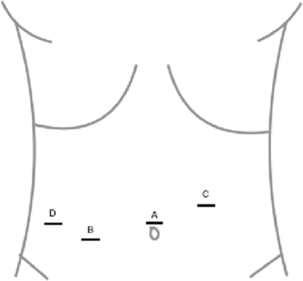
This is a typical AP (A) and lateral radiograph (B) of a 70 year old man with a 28° scoliosis who underwent posterior decompression, fusion, and instrumentation from L1 to L5. Notice that on the preoperative radiographs that the anatomy is very indistinct and each disk space is narrowed. C After placement of the first pedicle screw it was very difficult on AP and Lateral plain radiographs to confirm the correct placement of the first pedicle screw. It is difficult actually to determine even whether the screw is placed in L3 or L4, much less if it is in optimal position. Coronal CT reconstruction (D) and axial (E) CT images taken intraoperatively with E3D. Notice that there is no doubt that the axial image through L4 demonstrates the correct trajectory of the pedicle screw. In addition the coronal image confirms optimal placement of all 5 pedicle screws on the concave side of the lumbar spine from L1 to L5 before correction with a longitudinal 5.5 mm titanium rod. The E3D imaging leaves no room for ambiguity compared to fluoroscopy and plain digital radiographs, especially in the axial plane
The tertiary nature of our deformity cases included 30% revision cases with prior instrumentation—it is critical that the E3D allows for automatic subtraction of the prior metal implants and reduces metal scatter and artifact. We have used other intraoperative imaging systems that provide a good axial image except that the visualization of the spinal canal is totally lost as soon as a pedicle screw is inserted. In a residency training program, this negates the advantage of an intraoperative CT—it is mandatory to be able to confirm/reevaluate screw position relative to the canal. Figure 2 shows a case with an intracanal screw placed by robot at Elsewhere General. Even a resident with limited experience could prevent this complication with E3D, because the visual resolution of the spinal canal is unmistakable.
It is important to mention several limitations of our study. First, it was not possible to separate out either in the operating room record or the radiation records the amount of time utilized during surgery for the spine anatomy registration—this had to be indirectly measured from the total duration of surgery. Second, the two groups overlapped temporally so one might argue that the “learning curve” of robotics more directly influenced the robot only group. However, there were two additional surgeons who adopted robotics primarily in the E3D group, therefore, essentially two surgeons learning curves comprised the Group 1 complications and two additional surgeon’s learning curves were included in the Group 2 experience. Furthermore, the learning curve of adopting the new technology of intraoperative scanning and work flow was only present in the E3D Group. Therefore, this would serve to bias the results against Group 2, the E3D group, which in fact had only three of 80 cases require a return to the operating room for any reason (versus 11 of 80 patients for Group 1).
In our experience with 80 consecutive cases, the more unstable the spine, the more important it is to obtain the virtual construct based on intraoperative position—prone, without paraspinal muscle retraction, without respiratory excursion, after paraspinal dissection is completed, and without dynamic reference base (DRB) movement. In short, the more unstable the spine, the greater the advantage of E3D.
Comments (0)